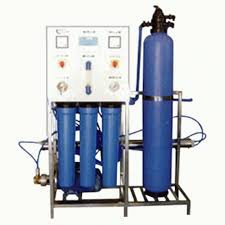
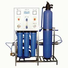
Hosur
TECHNICAL SPECIFICATION RO 250LITRE MS:
| 1 | Skid | |
| MOC | MS | |
| No. | 1 | |
| Make | Water Life | |
| Capacity | RO 250 liters. | |
| Type | Rectangle | |
| 2 | Feed Pump | |
| Type | Self Priming | |
| No. | 1 | |
| Make | CRI | |
| Capacity | 250 LPH | |
| Pressure | 3 KG/ CM2 | |
| Power Consumption | 0.5 HP | |
| 3 | Sand Filter | |
| Type | Vertical | |
| Diameter | 8 Inch | |
| Height | 44 Inch | |
| MOC | FRP | |
| Type of Operation | Manual | |
| Back wash Time | 10-15 minutes | |
| Size of multi port valve | ¾ ” | |
| 4 | Carbon Filter | |
| Type | Vertical | |
| Diameter | 8 Inch | |
| Height | 35 Inch | |
| MOC | FRP | |
| Type of Operation | Manual | |
| Back wash Time | 10-15 minutes | |
| Size of multi port valve | ¾ ” | |
| 5 | Micron Cartridge Filter | |
| Flow rate | 0.5 M3/hr. | |
| MOC | PP | |
| Length of Cartridge | 20” | |
| Dia. Of cartridge | 2” | |
| No. of Cartridge | 2 Nos. | |
| Rating | 20 Micron + 5 Micron | |
| Make | “Purtrex”, Osmonics, USA. | |
| 6 | Anti Scaling dosing system | |
| Pump | 1 Set | |
| Make | Aqua Italy / E-Dose / Hi-tech | |
| Quantity | 1 | |
| Type | Electronic Diaphragm Type | |
| Capacity | 0 to 4 LHP | |
| Quantity of Tank | 1 Nos. | |
| Capacity of Tank | 100 Liters | |
| MOC of Tank | HDPE. | |
| 7 | Pressure Pump | |
| Type | Vertical centrifugal multi stage | |
| No. | 1 | |
| Make | Grundfos/ CRI/ Procon | |
| Power consumption | 0.5 HP to 1.5 HP | |
| Flow | 0.5 M3 | |
| Pressure | 10 Kg/CM2 | |
| 8 | Pressure Tube | |
| Item | RO module consisting of membrane Housing With RO membrane mounted on skid. | |
| MOC | FRP | |
| Dia. | 4” | |
| Length | 40” | |
| Qty. | 1 Nos.
| |
| 9 | Membrane | |
| Type | TFC POLYAMIDE | |
| Size | 4” dia. x 40” | |
| Qty. | 1 Nos. | |
| Make | Filmtec, Desal® Osmonics , USA | |
| Rating | 0.0001 Micron. | |
INSTRUMENTATION:
| A | Digital Conductivity OR TDS Meter | |
| Quantity | 1 Nos. | |
| Maximum Temperature | 40 Degree Centigrade | |
| Location | RO Permeate. | |
| B | Flow Indicators | |
| Quantity | 1 Nos. | |
| Type | Float Type Panel Mounted. | |
| Maximum Op. Temp. | 40 Degree Centigrade. | |
| Measuring Points | RO Module Product Flow | |
| C | Pressure Gauges | |
| Quantity | 2 Nos. | |
| Range | 0-20 Kg / Cm2. | |
| Location |
| |
| D | High Pressure Switch And Low Pressure Switch | |
| Quantity | 1+1 Nos. | |
| Location | Before & After High Pressure Pump. | |
| E | Pressure Control Valve | |
| Location | Reject Water Line | |
| Nos. | 1 Nos. | |
| Make | Spring System USA. | |
| F | Auto Flushing switch with Solenoid Valve. | |
| G | Electronic Control Panel With A meter, Voltmeter, indicators, On off Switch | |
PIPE LINE
- CPVC pipe line from Feed Pump to Inlet of High Pressure Pump.
- SS pipe line from outlet of High Pressure pump to final water end point of system.
SKID
- MS box frame.


